
Here we are going to see about:
Resistors,Capacitors,Diodes,Ics,Transistors,series,parallel,series-parallel circuits,Basic component identification,relays,......
To begin with
Resistors :
For simplicity it is an electrical component that limits current flow.
A resistor is a passive two-terminal electrical component that implements electrical resistance as a circuit element. Resistors act to reduce current flow, and, at the same time, act to lower voltage levels within circuits. Resistors may have fixed resistances or variable resistances, such as those found in thermistors, varistors,trimmers, photoresistors and potentiometers.
The current through a resistor is in direct proportion to the voltage across the resistor's terminals. This relationship is represented by Ohm's law:

where I is the current through the conductor in units of amperes, V is the potential difference measured across the conductor in units of volts, and R is the resistance of the conductor in units of ohms (symbol: Ω).
The ratio of the voltage applied across a resistor's terminals to the intensity of current in the circuit is called its resistance, and this can be assumed to be a constant (independent of the voltage) for ordinary resistors working within their ratings.
Series circuits:
In a series configuration, the current through all of the resistors is the same, but the voltage across each resistor will be in proportion to its resistance. The potential difference (voltage) seen across the network is the sum of those voltages, thus the total resistance can be found as the sum of those resistances:


As a special case, the resistance of N resistors connected in series, each of the same resistance R, is given by NR. Thus, if a 100K ohm resistor and a 22K ohm resistor are connected in series, their combined resistance will be 122K ohm— they will function in a circuit as though they were a single resistor with a resistance value of 122K ohm; three 22K ohm resistors (N=3, R=22K) will produce a resistance of 3x22K=66K ohms.
Parallel circuit:
Resistors in a parallel configuration are each subject to the same potential difference (voltage), however the currents through them add. The conductances of the resistors then add to determine the conductance of the network. Thus the equivalent resistance (Req) of the network can be computed:

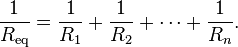
So, for example, a 10 ohm resistor connected in parallel with a 5 ohm resistor and a 15 ohm resistor will produce the inverse of 1/10+1/5+1/15 ohms of resistance, or 1/(.1+.2+.067)=2.725 ohms. The greater the number of resistors in parallel, the less overall resistance they will collectively generate, and the resistance will never be higher than that of the resistor with the lowest resistance in the group (in the case above, the resistor with the least resistance is the 5 ohm resistor, therefore the combined resistance of all resistors attached to it in parallel will never be greater than 5 ohms).
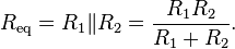
The parallel equivalent resistance can be represented in equations by two vertical lines "||" (as in geometry) as a simplified notation. Occasionally two slashes "//" are used instead of "||", in case the keyboard or font lacks the vertical line symbol. For the case of two resistors in parallel, this can be calculated using:
Series-parallel circuit:
A resistor network that is a combination of parallel and series connections can be broken up into smaller parts that are either one or the other. For instance,


Transistors :
A transistor is a semiconductor device used to amplify and switch electronic signals and electrical power. It is composed of semiconductor material with at least three terminals for connection to an external circuit. A voltage or current applied to one pair of the transistor's terminals changes the current through another pair of terminals. Because the controlled (output) power can be higher than the controlling (input) power, a transistor can amplify a signal. Today, some transistors are packaged individually, but many more are found embedded in integrated circuits.
![]()
More about electronics,arduino,c++,...... still to come!